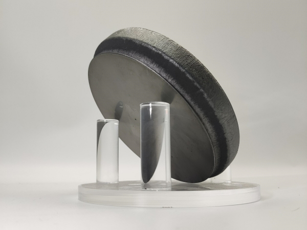
1. Invisible Performance Killer Hidden Beneath the Surface of Optical Components
Featuring an ultra-low coefficient of thermal expansion, high transmittance across ultraviolet and infrared bands, excellent chemical inertness and superior optical uniformity, fused silica serves as a core optical substrate for inertial confinement nuclear fusion, astronomical observation, military high-energy lasers, and semiconductor lithography equipment. Major global laser facilities, including the U.S. National Ignition Facility (NIF), France’s LM Megajoule Laser, and China’s Shenguang series of giant laser systems, are equipped with thousands of large-aperture fused silica lenses, optical windows and grating components.
Nevertheless, fused silica is a typical hard and brittle material. In the entire mechanical processing workflow from rough shaping, coarse grinding and fine grinding to polishing and cleaning, the extrusion and scratching of abrasive particles induce subsurface defects (SSD) beneath the component surface. Such micro-damages mainly include microcracks, plastic deformation layers, embedded polishing impurities, pits and residual stresses.
Pure and damage-free
fused silica has an intrinsic laser-induced damage threshold (LIDT) of over 100 J/cm². However, subsurface defects absorb laser energy massively, cause local thermal accumulation and distort internal photoelectric fields, drastically reducing the actual damage threshold to 5–15 J/cm². Initial laser damage sites will expand exponentially under subsequent pulsed irradiation, growing from micron-scale flaws to millimeter-scale damages in a short time and resulting in the scrappage of high-cost large-aperture optical components. As a core bottleneck limiting the output power and service life of high-power laser facilities, SSD must be eliminated and suppressed from the source, which requires a clear understanding of defect formation rules and classification characteristics.
2. Layered Structure and Defect Distribution of Polished Fused Silica Components
A typical polished fused silica component consists of five layers from the surface to the defect-free bulk substrate: polished surface layer, shallow flow layer, hydrolyzed Beilby layer, subsurface damage layer, and defect-free dense substrate. The hydrolyzed layer, composed of hydrated silica materials with a thickness of approximately 200 nm, completely covers underlying cracks and impurities, making conventional microscopes incapable of direct SSD observation. The overall depth of the subsurface damage layer generally ranges from 100 nm to several microns.
Characteristics of layered defects are classified as follows:
1. Shallow flow layer & hydrolyzed layer: Dominated by plastic scratches and embedded polishing powder impurities, belonging to mild shallow surface damage;
2. Deep SSD damage layer: Characterized by penetrating brittle cracks, concentrated residual stresses and internal voids, serving as the main initiation zone for laser-induced damages.
3. Mechanical Formation Model of SSD in Grinding Processing
The industry’s mainstream Lawn static indentation fracture mechanics model fully explains the entire initiation and propagation process of cracks under the action of abrasive particles:
1. Low-load stage: The abrasive equivalent indenter presses into the material, forming irreversible plastic zones without crack generation;
2. Critical median crack load P*: Vertical median cracks initiate directly beneath the indenter and propagate deep into the material;

3. Critical lateral crack load Pl*: Transverse lateral cracks expand outward in all directions;

4.Lateral cracks penetrate the workpiece surface to realize material removal. Unpenetrated radial and median cracks remain permanently, forming stable subsurface damages.
 Fig.1 Schematic diagram of dynamic grinding process
 In actual grinding conditions, abrasives undergo simultaneous rolling and sliding motions, and workpieces bear both normal pressure and tangential friction force, generating inclined trailing cracks and macroscopic continuous arc-shaped textures. Based on the evolution law of lateral cracks, the Tayyab research team proposed an optimized grinding model, which can simultaneously predict material removal rate and machined surface roughness and adapt to processing scenarios with different abrasive grain sizes.
4. Formation Mechanism and Optical Hazards of Four Major Types of Subsurface Defects
| Defect Type |
Formation Cause |
Core Negative Impacts |
| Scratches |
Abrasive scratching and friction of residual hard particles during polishing |
Induce local electric field enhancement and serve as initiation sites for laser damage; stress concentration easily expands into deep cracks |
| Microcracks |
Processing thermal and cold stresses, external extrusion, and expansion of original micro-defects |
Significantly reduce tensile and compressive strength of materials; cracks proliferate and penetrate rapidly under laser irradiation |
| Pitting Spots |
Abrasive impact and embedding, exposure of internal bubbles and inclusions |
Aggravate optical path scattering and reduce light transmittance; cause local laser focusing and temperature rise |
| Pits |
Uncontrolled laser processing parameters, uneven acid cleaning, and rupture of internal bubbles |
Form light energy concentration hotspots and easily induce irreversible optical damages |
5. Empirical Formula for Engineering Estimation of SSD Depth
Semi-empirical formulas summarized from extensive grinding experiments can quickly estimate damage depth and predict processing damage magnitude without precise detection:
1. Abrasive particle size correlation formula:

(where d refers to abrasive particle size);
2. Roughness proportional rule: For glass/ceramic grinding with loose SiC abrasives, the SSD depth is approximately 3.93±0.17 times the surface roughness;
3. Miller Model: Establishes a quantitative correlation between SSD depth, surface roughness (SR), elastic modulus (E), hardness (H), abrasive cutting angle and processing load, enabling accurate calculation of damage depth under various working conditions.
6. Conclusion
In summary, subsurface defects in fused silica optical components are latent damages induced by multi-physical field coupling during ultra-precision machining. Dominated by microcracks, residual stresses and impurity defects, such damages degrade optical performance, reduce laser-induced damage thresholds, shorten component service life, and severely affect the operational stability of high-end optical and laser systems. This paper systematically clarifies the formation mechanism and evolution law of machining damages in fused silica, defines the correlation between material properties, processing techniques and subsurface defects, and provides reliable theoretical basis and engineering guidance for process optimization, defect suppression and precision fabrication of fused silica components.

Aiming at the rigorous requirements of
fused silica machining and high-end optical applications, JXT provides high-quality fused silica, optical glass substrates and precision optical components. Adhering to strict raw material selection and mature ultra-precision machining technology, the company effectively controls subsurface microcracks, residual stresses and other machining damages. Our products feature low defect density, high light transmittance, high laser damage threshold and excellent optical consistency. They are widely applicable to laser equipment, precision optical instruments, optoelectronic communication and scientific research scenarios, and support customized production of various specifications and high-precision products. By eliminating performance risks caused by machining damages, our high-quality optical materials and components ensure stable operation of high-end optoelectronic equipment.